A detailed description of the geometry in not appropriate for this manual but an overview will help you to understand how the code works and how it is organised. The geometry has to service the following basic requests:-
The geometry design all flows from two guiding principles:-
These principles appear to be in conflict: each boundary has to be dealt with by one routine yet each is shared by two regions each with their own routine. The solution is to assign priorities to each region. The only requirement is that two neighboring regions have different priorities. The boundary is owned by the region of higher priority; code dealing with the lower priority region must call the higher priority one to deal with the surface. In this scheme each region is defined by 2 types of boundary:-
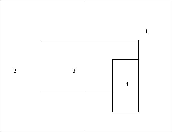
As an illustration consider diagram 12.1 where the numbers represent both the regions and their priorities. The table below shows which boundaries are internal to each region.
Region Internal Boundary 1 2 3 4 2 3 3 4 4 None
So the geometry is an embedding geometry, regions of higher priority are
embedded in regions of lower priority. As a specific example, the
acrylic vessel is considered to be a solid sphere of
acrylic in which is embedded a sphere of D![]() O , a set of belly
plates and two concentric cylinders that represent the chimney. Of course,
the concept of embedding can be nested. For example, the detector starts as a
solid ball of rock in which are embedded a counting room and the inner
darkness. Within these regions further regions are embedded, and the process
repeats until a complete model of the detector has been assembled. So,
strictly speaking, all other regions are internal to the rock. However, the
only internal boundaries that have to be dealt with here, or in any other
region, are those that are directly visible: the rock cannot `see' individual
PMTs!
O , a set of belly
plates and two concentric cylinders that represent the chimney. Of course,
the concept of embedding can be nested. For example, the detector starts as a
solid ball of rock in which are embedded a counting room and the inner
darkness. Within these regions further regions are embedded, and the process
repeats until a complete model of the detector has been assembled. So,
strictly speaking, all other regions are internal to the rock. However, the
only internal boundaries that have to be dealt with here, or in any other
region, are those that are directly visible: the rock cannot `see' individual
PMTs!
For panel zones and PMT hexagons, it is the `array of' that embeds. Internally these regions are divided up into a set of tessellating sub regions that all have the same priority. The concept of boundary consistency is not compromised however, as the consistent handling of internal boundaries is part of the `array of' concept. For example, a panel is viewed as a honeycomb of hexagonal prisms, each having its own serial number but all having the same priority. The boundary of every hexagon is handled by the same code, thus ensuring consistency.